Jk flip two circuit following active low clear timing diagram flops uses aa solved Draw the circuit diagram of jk ff using nand gates. derive its Flip flop jk sequential circuit logic slave master nand symbol basic connect gif
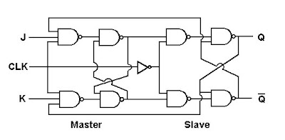
Draw the circuit diagram of JK FF using NAND gates. Derive its
Jk flip flop
Jk ff table excitation nand using characteristic flop flip state condition race around
T-ff to jk-ffJk ff multisim Implement a j-k ff using a dffFlip ff3 ff1 flops ff2 nand three gate solution.
Jk flip flopFlip jk flop circuit sequential input equation using Jk ff condition race diagram around nand using avoidingInput equation of sequential circuit using jk flip flop(हिन्दी ).

Jk flip flop verilog schematic ff
[solved] design sequential circuit using jk ff design a sequentialJk flip-flop counter synchronous circuit electronic circuit, png Ff jk using schematic maximum prevent counter reaching beginning start after circuitlab createdJk tnx.
Jk flop flip circuit diagram master rgpv mcaJk flip flops schematic simpler why use when circuit flipflop circuitlab created using Jk flip flop truth table and circuit diagramJk sequential flops inputs.

B): logic circuit diagram of memory element for jk-ff at 75%
Rgpv mca: master jk flip flop circuit diagramFlip flop jk truth table circuit diagram shown below Solved: the three j-k flip-flops (ff1, ff2, ff3) and the nand gateDff implement.
Draw the circuit diagram of jk ff using nand gates. derive itsJk table excitation flip flop equation characteristic ff state nand circuit using diagram draw derive consider shown below need find Draw the circuit diagram of jk ff using nand gates. derive itsSolved: chapter 5 problem 10p solution.

Solved for the following circuit that uses two jk flip flops
.
.